


XML Gauge Design for FS
Contents:
Basic
panel.cfg manipulation
Panel redesign
Gauge creation
Some sample gauges
The new FS2004 XML format
Aircraft gauge design has been one of the few areas of FS that has been out of bounds to most designers.
The gauge format from FS98 to FS2002 comprised of a GAU file containing the code and bitmaps. Gauge Browser allowed users to open the GAU files, extract the bitmaps and repaint them but this was of limited use. You could redesign a radio box without much problem but reworking an ASI was only feasible if you then rewrote the code to match needle movement with the reworked dial. If you were proficient in C++ coding this was no problem but not many users are and so gauge design was mostly a black art practised by a few devotees (like Dai Griffiths).
|
ASI Gauge for the PA27 Aztec F The bitmap was built in PaintShop Pro using photographs from the real aircraft. A separate bitmap was made for the needle.
|
With FS2004 gauge design moved over to XML coding. The XML code and bitmaps are usually bundled into a CAB file - you will see a lot of these in the FS2004/Gauges folder. This is a good thing because CAB files can be opened easily enough to reveal the bitmaps and XML files inside. Some CAB files contain files for just one instrument but others contain files for the whole panel set. The default Beech_Baron.CAB file contains 480 files in total - 68 XML gauges and 412 associated bitmaps whereas the FS9_Clock CAB contains just the clock XML code and four bitmaps.
How to use the gauges
There are several ways you can utilise the default gauges for building your own panels.
You can use the existing instruments in your own panel just by adding the gauge you want in the CAB file to the panel.cfg file. The format is fairly straightforward - you just need the name of the CAB file and the name of the XML instrument within it.
Say you wish to use the clock from the default Boeing 747-400. The CAB file is Boeing747-400.cab and the XML file is called clock.XML. All you do is create a new gauge in your panel.cfg file like so:
Gauge55=Boeing747-400!Clock, 1, 1, 113, 113
In this case the CAB file name is inserted, followed by a "!" and then the name of the XML file. The four numbers following show the X and Y pixel location for the top left of the associated bitmap followed by the width and height in pixels that you wish to size the gauge to.
This is very easy and you can build up a complete panel using the default instruments in FS2004 - or by "borrowing" gauges from any add-on aircraft you have. Many add-on aircraft have customised gauges which may suit you nicely but be careful - some commercial packages may have gauges that won't work in your own panels. Also be careful if you wish to distribute your aircraft or panel because other users may not have the add-on aircraft you have borrowed gauges from. You could include these gauges in your upload but you WILL require permission from the original gauge designer.
Building your own
If there are no suitable gauges in your FS collection for your project then you could build your own.
You can extract the XML code and bitmaps for a similar gauge and put them into a folder for modification. This is just what I did when I decided to rework the Piper Aztec panel supplied by Fred Choate and turn it into a more accurate representation of the aircraft I fly.
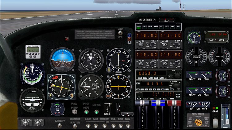
The first screenshot shows the original panel supplied with Fred's Aztec. It's a perfectly good panel but it is quite different from our own Aztec - hence the desire to see what could be done to modify it.
The Aztec Project
The list below shows the original changes I wished to make. The this list is bigger than I anticipated but after careful checking of our aircraft's panel I could see more variation than I had realised. The finished panel will have 63 gauges/switches in it of which 38 will be rebuilt - I see no need to replace default (or Fred's) gauges that are already made and are accurate.
Some gauges will be easy and some a little more tricky. The full list of alterations, with my estimation of difficulty shown, is:
|
1.
Build new ASI to read knots. |
Finished |
Easy |
Easy gauges are those that simply read data from FS (like the ASI and VSI) or interactive gauges that just have an on/off action (like most switches). Moderate gauges like the autopilot have several click spots that trigger different actions, some of which may be interconnected. Tricky gauges are those that may interact with another gauge (left mag switch ON and right mag switch ON = Mags BOTH) or a toggle switch like the flap lever.
Some bitmaps from the actual aircraft have also been pasted on to the main panel bitmap - some containing units that cannot be replicated in FS and so will remain dummy dials (the gyro slave unit and the door warning panel being the two major ones). Other bitmaps for checklists have been added to give a more personal touch.
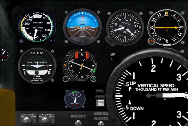
The new panel
Below is the new panel that the Aztec will sport in the next week or so - and the one I am now primarily working on.
As well as the new radio stack the photo shows many changes from the shot above. Most of the default gauges have now gone and have been replaced by gauges built directly from photo's of the Aztec panel. Although similar the right side of the panel has been entirely rebuilt - from the fuel and oil gauges down through the engine dials. On the main section the autopilot and suction gauges are now proper Piper items - as is the throttle unit.
Click the image below to see full size.
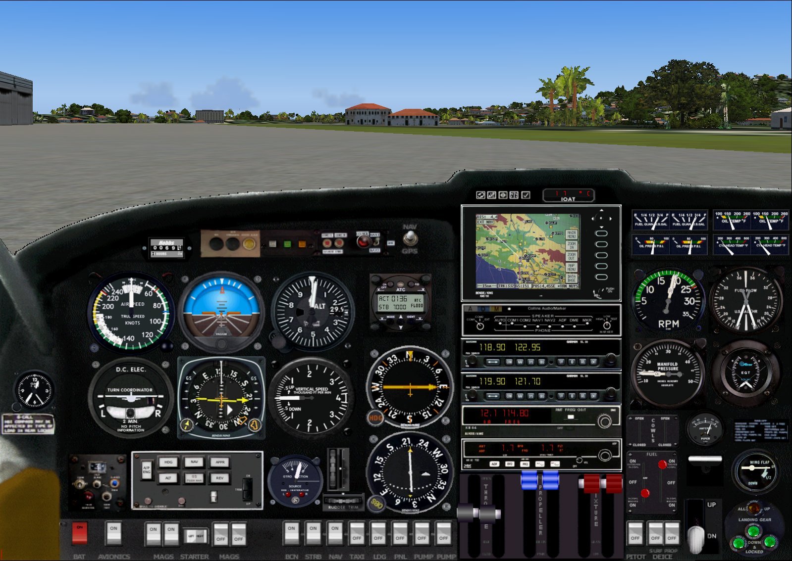
As described earlier most of the new dials and gauges are now in place and most are now working. Only the King KMD150 GPS unit remains to be started but although the rest are present there is still some code tweaking to be done to eliminate problems. The problems lie in two areas - gauges that don't display correctly or gauges that don't work as intended.
Display faults include the Cowl Flaps (no knobs showing) the fuel tank selector (levers showing but in the wrong positions) and magnetos (starboard mags showing off despite the engine obviously running). In all these cases the code requires that the actual condition of these items be checked first in FS and the display reflect the condition. They can't just default to OFF.
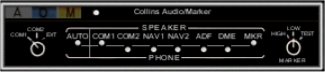
Present work is now on the radio stack and this is coming along better than expected. The Collins Audio panel in mostly complete with all but the left hand knob operational. In the shot below COM1 and MKR are set to on - otherwise you wouldn't hear them!
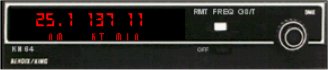
The KN64 DME is working but not quite like the original unit which can be tuned independently of Nav1. On the real KN64 distance and frequency are shown with the selector in the FREQ position - distance, speed and TTS are given when the selector switch is moved to the GS/T position. RMT gives the same values but for NAV2.
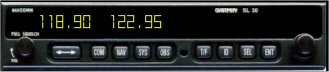
The Garmin SL30's are going to be tricky. I have the displays working but have yet to find a way of combining the COM and NAV tuning functions. At the moment the units can display COM freqs or NAV freqs by pressing the COM and NAV buttons but only the COM frequencies are tunable.
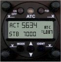
The dial I thought would be hardest was the Filser TRT600 Mode S Transponder but that worked out far better than I had hoped. The LCD screen looks quite effective! It just needs a slight tweak to make the height text more readable. The dial actually says FL087 but it's not that obvious!
Now compare the above shots with the real aircraft panel below. Don't forget this is an old Aztec so the panel looks really tired in some areas. Also note the panel is in a hybrid state as the radio units are still a mix of old and new. Once the old Collins COM/NAV boxes have gone the KMT150 unit will be repositioned into the centre stack.
Click on the image to see it full size.
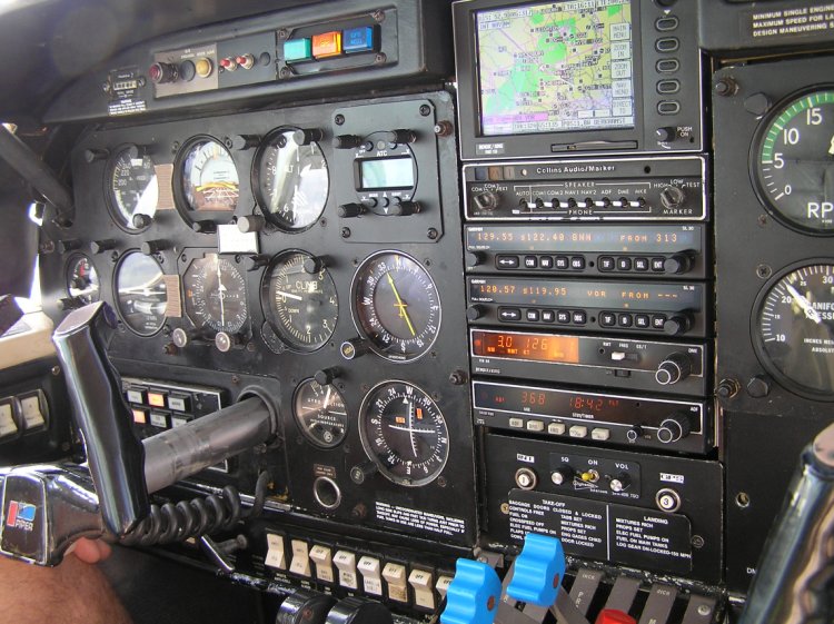
Note that 100% accuracy is never possible because some switches and indicators in the real aircraft are on the overhead panel or below the throttle unit. You can mimic these with popup windows if you want but here I am staying with the one panel to avoid lots of window swapping (annoying when you are busy on approach or take off).
A simple gauge rework
Let us look at an ASI.
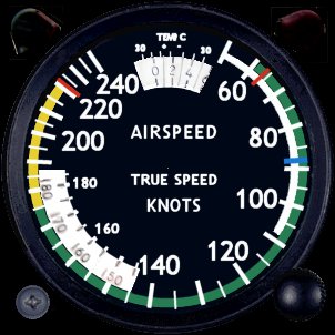
To build a basic ASI all your need is to design an ASI face and a separate needle. More complex ASI's may have an adjusting knob to allow a mouse click to change the pressure. If you are really clever you could also add the Kohlsman insert for adjusting the dial to read TAS instead of IAS - but that is getting complicated!
Here are the bitmaps for my Aztec ASI. I made this because the excellent Aztec aircraft built by Fred Choate for FS2004 has an ASI that reads in MPH whereas the aircraft I fly has an ASI in Knots. I originally used Fred's dial and simply altered the XML data to adjust the needle to read knots and not MPH but I then decided to rebuild the bitmap to look more like the real thing.
Bitmaps are usually 256 (8 bit) to keep file sizes down but this isn't critical. Remember that pure black (0,0,0) should not be used except for those parts of the bitmap you wish to be transparent.
ASI face and needle. ![]()
As well as the bitmaps you also need the XML code to drive the animation. The code for the ASI looks like this:
<Gauge
Name="airspeed" Version="1.0">
<Image Name="PA27_ASI_background.bmp"/>
<Element>
<Position X="151" Y="151"/>
<Image Name="PA27_ASI_needle.bmp" PointsTo="North">
<Axis X="10" Y="126"/>
</Image>
<Rotate>
<Value Minimum="0" Maximum="240">(A:Airspeed
select indicated or true,knots)</Value>
<Failures>
<SYSTEM_PITOT_STATIC Action="0"/>
<GAUGE_AIRSPEED Action="Freeze"/>
</Failures>
<Nonlinearity>
<Item Value="0" X="151" Y="30"/>
<Item Value="55" X="206" Y="38"/>
<Item Value="60" X="231" Y="55"/>
<Item Value="70" X="254" Y="81"/>
<Item Value="80" X="270" Y="112"/>
<Item Value="90" X="277" Y="152"/>
<Item Value="100" X="271" Y="187"/>
<Item Value="110" X="254" Y="221"/>
<Item Value="120" X="222" Y="254"/>
<Item Value="130" X="183" Y="273"/>
<Item Value="140" X="134" Y="276"/>
<Item Value="150" X="94" Y="263"/>
<Item Value="160" X="61" Y="238"/>
<Item Value="170" X="38" Y="206"/>
<Item Value="180" X="27" Y="172"/>
<Item Value="190" X="25" Y="145"/>
<Item Value="200" X="29" Y="119"/>
<Item Value="210" X="37" Y="98"/>
<Item Value="220" X="51" Y="75"/>
<Item Value="230" X="63" Y="60"/>
<Item Value="240" X="80" Y="47"/>
</Nonlinearity>
<Delay DegreesPerSecond="360"/>
</Rotate>
</Element>
<Mouse>
<Help ID="HELPID_GAUGE_AIRSPEED"/>
<Tooltip ID="TOOLTIPTEXT_AIRSPEED_KNOTS"/>
</Mouse>
</Gauge>
The code isn't complicated and, if you wish to change it for your own design, you only need to alter a few lines.
|
Line
2 - |
Change the name of the bitmap to that of your own dial bitmap name. |
|
Line
4 - |
This is the position in pixels on the main bitmap for the pivot point of the needle. In this case 151, 151 is the centre of the bitmap as it is a 302 x 302 image. |
|
Line
5 - |
The name of the needle bitmap. You also specify the position it defaults to at rest - in this case North. |
|
Line
6 - |
The position in pixels on the needle bitmap at which rotation centres. In my case this is 10 pixels across and 126 pixels down to the pivot.. |
|
Line
9 - |
Min
and max values of the ASI followed by the measurement parameter.
The value in brackets is important as this tells FS what units you
are using. |
|
Lines
15 to 35 - |
Determines needle movement. This nonlinearity section gives us a great degree of flexibility in making gauges work so I'll describe it in a little more detail. |
The first line tells us that when Item Value=0, X is 151 and Y is 30. What this means is that at 0 knots the needle should point towards pixel value 151,30 on the main bitmap. At 55kts the needle should point towards pixel 206,38. This is very useful on an ASI because the spacing between speeds varies around the dial and nonlinearity allows us to adjust the needle movement for this variation. If the values were equally spaced then you would only need to specify the first and last values.
The nice thing about specifying the pixel position is that it isn't critical - you can specify any point as long as it is on the projected path of the needle. For 60kts I have picked 231,55 but I could equally have picked 218,70 - it doesn't matter.
That is all there is to it - working code and some bitmaps. To put it all together you can place your bitmaps and XML file in a folder and use a CAB creation utility like VCAB to create a proper CAB file (you will also need the CABDir.exe file from the XML SDK). If you make further gauges you can add the XML and bitmap files to the same CAB or keep them separate - it's entirely up to you. Drop the CAB file into the FS Gauge folder, add the new line to your panel cfg file and start FS...
Yep - it doesn't always work out the first time!
In the shot above the new ASI is working and the speed readings are fine - remember that you have to check the full speed range to make sure all is well. The VSI went a bit awry. Note it is greatly oversize (wrong values in the panel.cfg file) but that the needle is also pointing to the right instead of left - it worked fine but from the wrong side of the gauge!
This fault was caused by the Nonlinearity table values being listed in the wrong order - you have to reverse the values for gauges that have needles that do not rotate clockwise.
XML Weight Gauge in Cessna 172
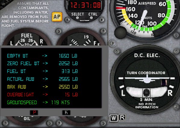
The gauge is a simple box with text data for various aircraft weights. It is toggled by the "W" icon bottom left of the Turn and Slip. The position of the icon and data box are set in the panel.cfg file like any other gauge so they can be adjusted for every aircraft.
The figures are self explanatory really. Blue figures are actual values and yellow are the limits. The red Overweight box shows the aircraft at 15lb above Max AUW but will be blank when within limits.
The
P and K buttons alternate between pounds and kilos. In the kilos display
(shown below) everything is the same except that I have replaced groundspeed
with magnetic wind velocity.
Same gauge in the Boeing 747-400
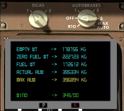
The display in the 747-400 works just as well and I have created space for heavier aircraft like the A380 that will probably exceed 1,000,000 lbs in weight (the 747 is 895,000lbs MAUW).
Like all windows the display can be resized or moved easily with the mouse.
Download the Weight Gauge
If you want to try the gauge click HERE to download it. It's a huge 3k!
Just plonk it in your FS Gauges folder.
To add the gauge to any aircraft's panel open up the panel.cfg file and add the following sections. The example used is for the default C172 with the new lines shown in red..
1. Title section
[Window
Titles]
Window00=Main Panel
Window01=Radio Stack
Window02=GPS
Window03=Annunciator
Window04=Compass
Window05=Mini Panel
Window06=Weight
Add a new section called Weight at the end of the windows title section. Increment the number accordingly.
2. To place the toggle icon go to the main 2D panel (Window00) section and at the end of the gauge listing add this new line:
gauge40=SimIcons!ATC
Icon, 340, 280
gauge41=SimIcons!Map Icon, 354, 280
gauge42=SimIcons!Avionics Icon, 399, 280
gauge43=SimIcons!GPS Icon, 413, 280
gauge44=SimIcons!Compass Icon, 427, 280
gauge45=Weight_JW!WeightIcon, 145, 255,
12, 12
Note: For aircraft other than the C172 you will have to alter the 145 and 255 values to locate the icon in a suitable position. Experimentation may be needed here unless you have a panel design tool. If you accidentally relocate the icon over another gauge it may not appear (happens over gauges that refresh quickly).
3. Add the Window section for the new gauge. With the C172 I created a new section 6 as follows:
[Window06]
size_mm=150, 100
window_pos=0.35, 0.60
background_color=0,0,0
ident=273
visible=1
gauge00=Weight_JW!AC-weight, 0, 0
Again number the panel incrementally to suit the aircraft panel you are using. You can play with the variables if you wish. In the example above the weight panel appears on loading the aircraft but if you prefer it off then use visible=0. You can also change the window_pos line to make the panel pop up elsewhere on the screen - or simply drag it with the mouse. Changing the line would be a permanent solution - if you drag with the mouse the new position will not be remembered for your next FS session.