


FS2004 Scenery
GMax Tutorial (Basics)
GMax Basics
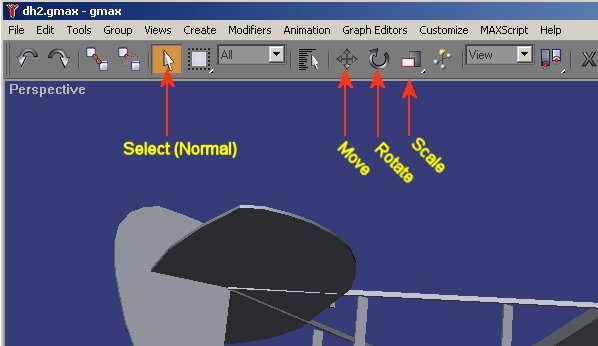
This tutorial will show you the power and versatility of the Move, Rotate and Scale buttons on GMax.
Stage 1 - Create an Object
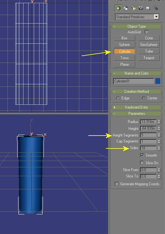
Create a simple cylinder with four or five length sections. It doesn't matter which viewport you create this in because we will use the rotate button to align it correctly.
|
Here I have used 5 segments and set the number of sides to 18 - a reasonable number for small structures as GMax automatically smoothes the edges to give a rounded appearance. If you create the object by dragging the mouse on screen you do not need to get the position or dimensions exactly right as you can adjust the values in the Parameters box shown on the right of the screenshot. If you untick the smooth box GMax will not attempt to smoothen the edges and you then get a true 18 sided object. Slice allows to to create a partial cylinder by setting the angles. A Nissan Hut could be created by only using half a cylinder (or slightly less). When you have finished creating the shape click on the Select button at the top to release the Cylinder creation button. |
Stage 2 - Move an Object
In the Front viewport click on the cylinder you created to highlight it. This will be shown in the Perspective Box by a white outline and in the other three boxes by the object turning white and axis arrows appearing.
Now click on the Move button. You will see the axes arrows change colour - they become red, green and blue).
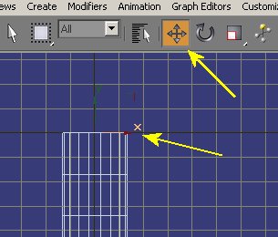 |
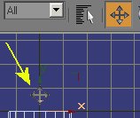
If you move the mouse over either axis you will see it change shape to mimic the Move icon. This allows you to click and drag the object along that axis.
|
|
|
|
Stage 3 - Rotate an Object
Rotate is similar to Move except that you have control over all three axes in any viewport. Careful positioning of the mouse is needed to select the right axis!
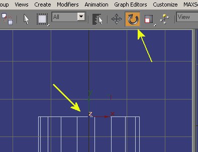 |
In the example on the left the axis facing towards the viewer is selected (the Z axis) and the Z has changed orange to show this. Dragging the mouse on the Z axis will cause the object to rotate either clockwise or anticlockwise as seen in the viewport. Dragging on the Y axis (Green) will cause the object to rotate around its lengthwise axis. Dragging on the X Axis (Red) will rotate the object towards or away from the view. Experiment to see what I mean! |
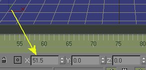
As you rotate the object the amount is shown on the axis bar at the bottom of the screen.
Note: It can sometimes be awkward to rotate an object exactly 90 degrees because GMax may stick on 89.5 or 90.5. If this happens rotate the object by say 60 degrees and then drag it a second time by 30 degrees.
Stage 4 - Adjust Scale
Scale in its basic use is not axis critical and you can select any that show on the screen. As you drag the axis the object will shrink or expand uniformly. This is self evident if you try it out so no need for screenshots.
When Scale is selected the axis readouts (shown above) show the relative percentage increase/decrease from default object size.
Stage 5 - Going down one level
Although the three buttons have a certain limited functionality as described above they really become far more useful when applied to specific areas of your object.
You do this by splitting your object up into editable polygons. When you start working at sub object level creative abilities go ballistic!
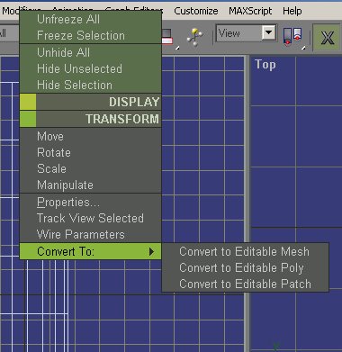 |
First let us take a look at the cylinder we have already created. RIGHT click on the cylinder to bring up the object menu (an alternative option to using the toolbar). Go down to Convert To and select Editable Poly. You won't see any change in the object itself but you WILL see the menu's on the right of the screen change quite a lot. This is because the object is now Modified and the menu selection has jumped from the Create tab to the Modify Tab on the menu bar.
|
|
|
The menu bar becomes a bit important now so I will take this chance to cover the options. The top arrow shows the second tab of the right menu bar - called Modify. You will spend some time in this so remember the name. The first tab (called Create) is always active when you start the program as it is assumed you will want to create a shape as the first step in any project. The other tabs are for Hierarchy, Motion, Display and Utilities but you will probably only use Hierarchy in any FS work - and that for animations only. The second arrow shows that the main panel for your object now calls it an Editable Poly. This panel is the Stack and it is called that because many modifications can be made to an object. The third arrow shows the Editable Poly's selection choices. You will have already used this if you have followed the house tutorial because you will have selected the Polygon icon to Extrude bits of the house. I want you to select Vertex instead.
|
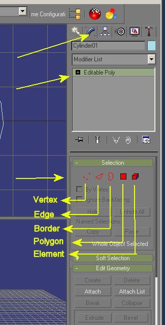
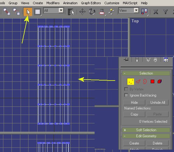
Vertex selection results in blue dots appearing on every vertex of the part. Now go up to the main menu and reselect the Select Object button.
|
Stage 6 - Partial Selection
With the object now in Editable Poly mode and the objects vertices highlighted we can now apply the Move, Rotate or scale functions to a specific Vertex or group of vertices.
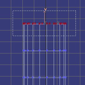 |
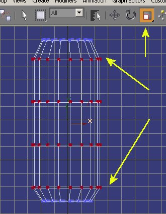
To select the vertices we drag a box around the ones we require. Care is needed here because the box will highlight ALL the vertices in the area - not just the ones we see in a viewport. In the example here the whole top row of vertices will be selected. If we now select Move, Rotate or Scale we will get a very different set of effects. |
Stage
7 - Move Partial Selection
 |
With the vertices still highlighted and the Move button selected we can alter the position of the whole top section of the cylinder. In the example here I have put the mouse on the X axis and offset the top of the cylinder by dragging. Had I selected the Y axis I could have dragged the cylinder upwards - effectively making it longer. |
Stage 8 - Rotate Partial
Selection
Rotating a partial selection can be fun but be aware of the axis you choose for rotation!
|
|
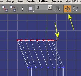
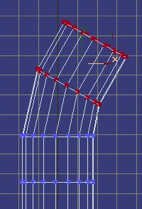
In this example I have now selected the top two rows of vertices. The Rotate button has then been selected and I have moved the mouse over the Y axis and dragged. The result is that the top two rows have rotated around the Y axis - effectively twisting the cylinder. If I had chosen the X axis things would have gone a little differently.. |
|
|
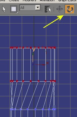
...as you can now see. The X axis shift rotates the selected items again but rather more complex effect. If we then pick the Move tool we can further adjust the selected parts. I'll move them right a bit so you can see that we have a more obvious application for this method.. |
 |
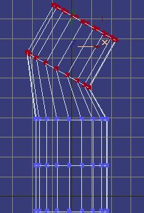
The shift to the right now gives us the possible beginnings of a length of bended pipe. A few further Move and Rotate operations to other selections on the object and we have a fairly worthwhile result. |
Step 9 - Scale partial Selection
You can see that with various selections of vertices and a combination of Move and Rotate you have the beginnings of more complex modelling. Scale is also quite powerful.
|
|
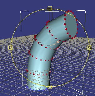
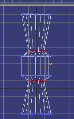
Here I have selected all the middle rows of vertices in the cylinder and used the Scale button to drag them outwards. This is the beginning of many possible objects - from a jet engine to a cooling tower (scaled inwards rather than outwards).
|
 |
We need not restrict ourselves to such blocks of vertices either. We could select one row and then, by holding down the CTRL key, drawn a second box around any other row. Rescaling just the two rows of vertices on the left produces a very different effect.
|
I need not go any further with this tutorial because to can easily see the potential of even these basic commands. I used very few of the actual Modifiers in GMax because many manipulations could be carried out from these basic techniques extremely effectively.